page.layout: post
page.title: Filter Ping
page.date: 2021-06-19 00:00:00 +0000
page.url ⛓️: /2021/06/19/4-filter-ping/
page.content_id: 4
page.author: Tyler
page.type: Praxis
page.ascii: !
page.x: 5
page.y: 29
page.class: red
page.attributes: transistor, filter
This log describes how to create a percussive sound with an envelope and a filter. Any envelope and filter will do. You’ll also need a way to trigger the envelope, along with a way to listen to the output of the filter.
Ingredients
- Envelope generator
- Filter
- Envelope trigger
- Audio interface
Filter Ping Example
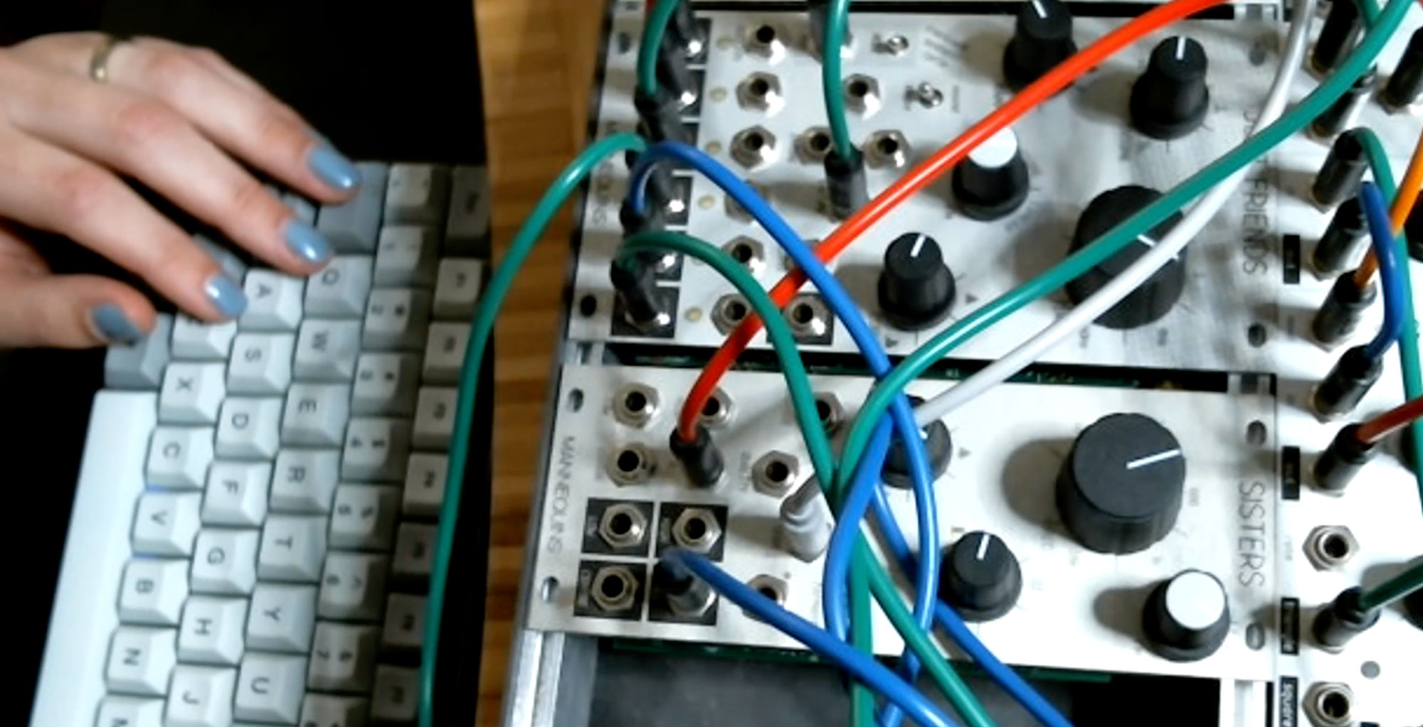
- Set your envelope to a very short attack. Something between
0msand10msshould do. Set your decay and/or release (depending on your instrument) to have a smooth curve.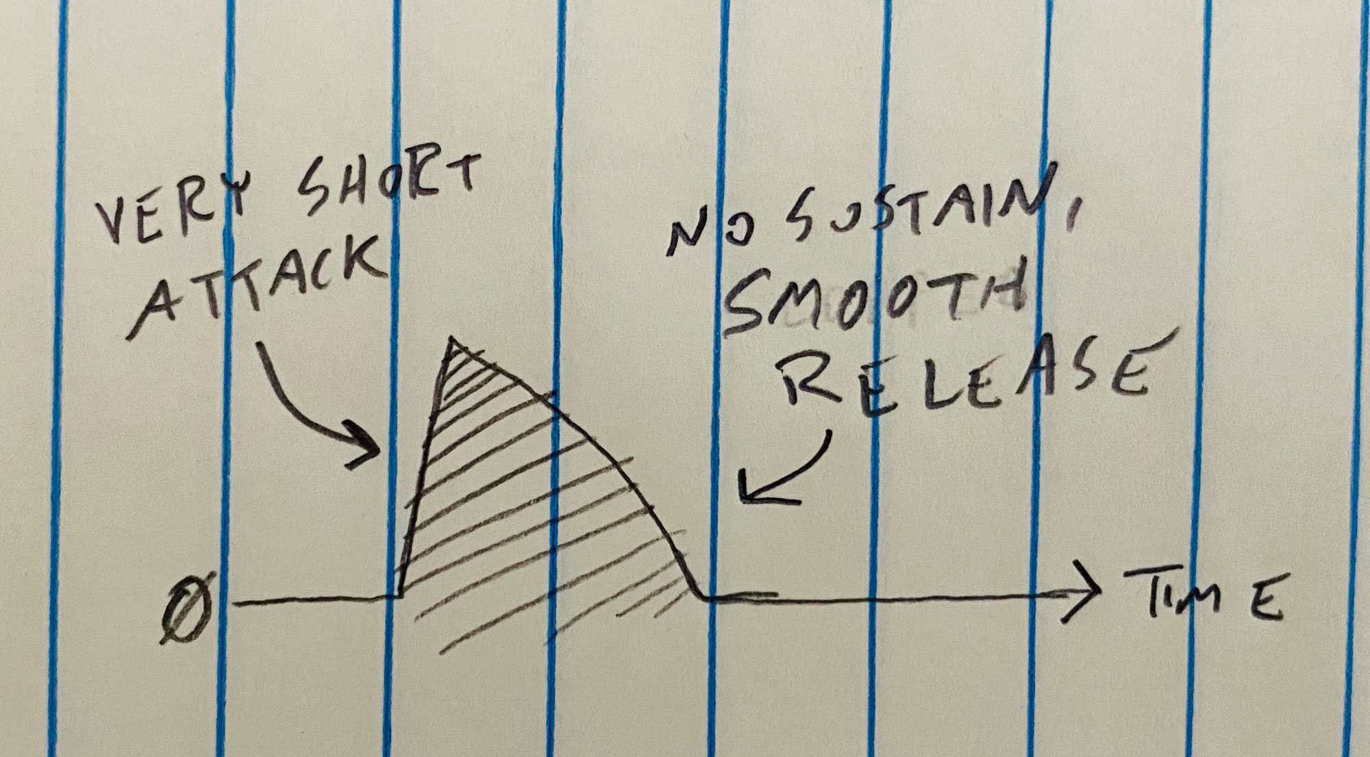
- Route this envelope’s output to the filter’s input. (This may feel counter-intuitive as typical use of a filter has the synthesist routing audio-rate signals here.) Route the filter’s output to your audio interface so you can hear it.
- Increase your filter’s resonance to the maximum, then dial it back until just after it quiets down.
- Trigger the envelope.
It may look like this:
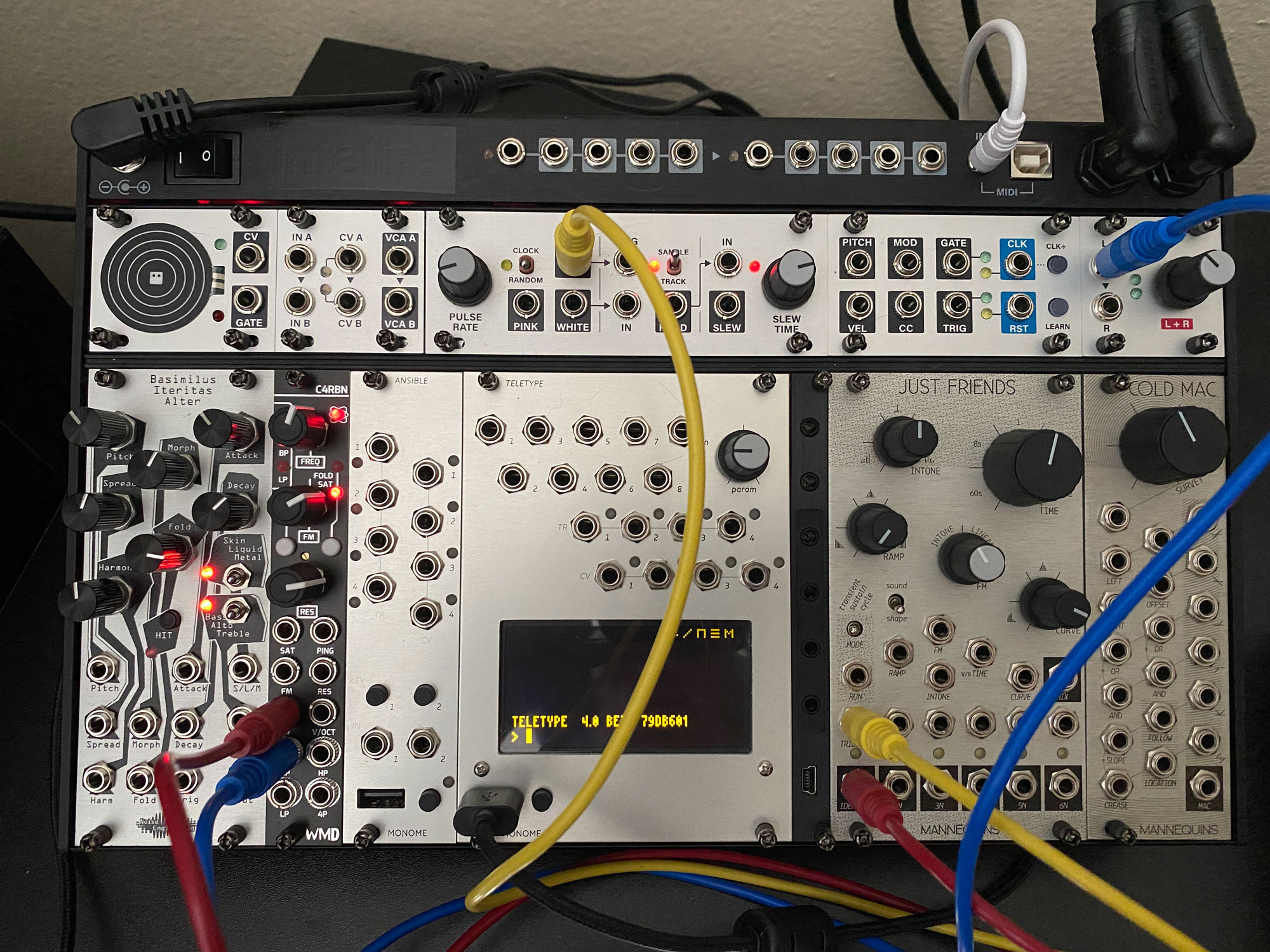
- Yellow Cable: clock output (here randomized) to envelope trigger input.
- Red Cable: envelope output to filter input.
- Blue Cable: Filter output (here band pass) to audio interface.
And it may sound like this:
Advanced Filter Ping Example
Following the same concept as before, now add modulation. Here, we use a Teletype but something like a Maths or any other envelope generator/follower will suffice. Teletype is standard issue at the University of Maps for its versatility and ability to “self-document” behavior in patch photographs.
- (Start from the above “Filter Ping” patch.)
- Send the clock output to a buff mult instead of directly into the envelope input.
- Route one of the buff mult outputs to the envelope input.
- Route another buff mult output to Teletype input #1.
- See photograph for Teletype scene & script implementation.
- Route Teletype CV #1 output to a modulation target such as filter FM or frequency.
It may look like this:
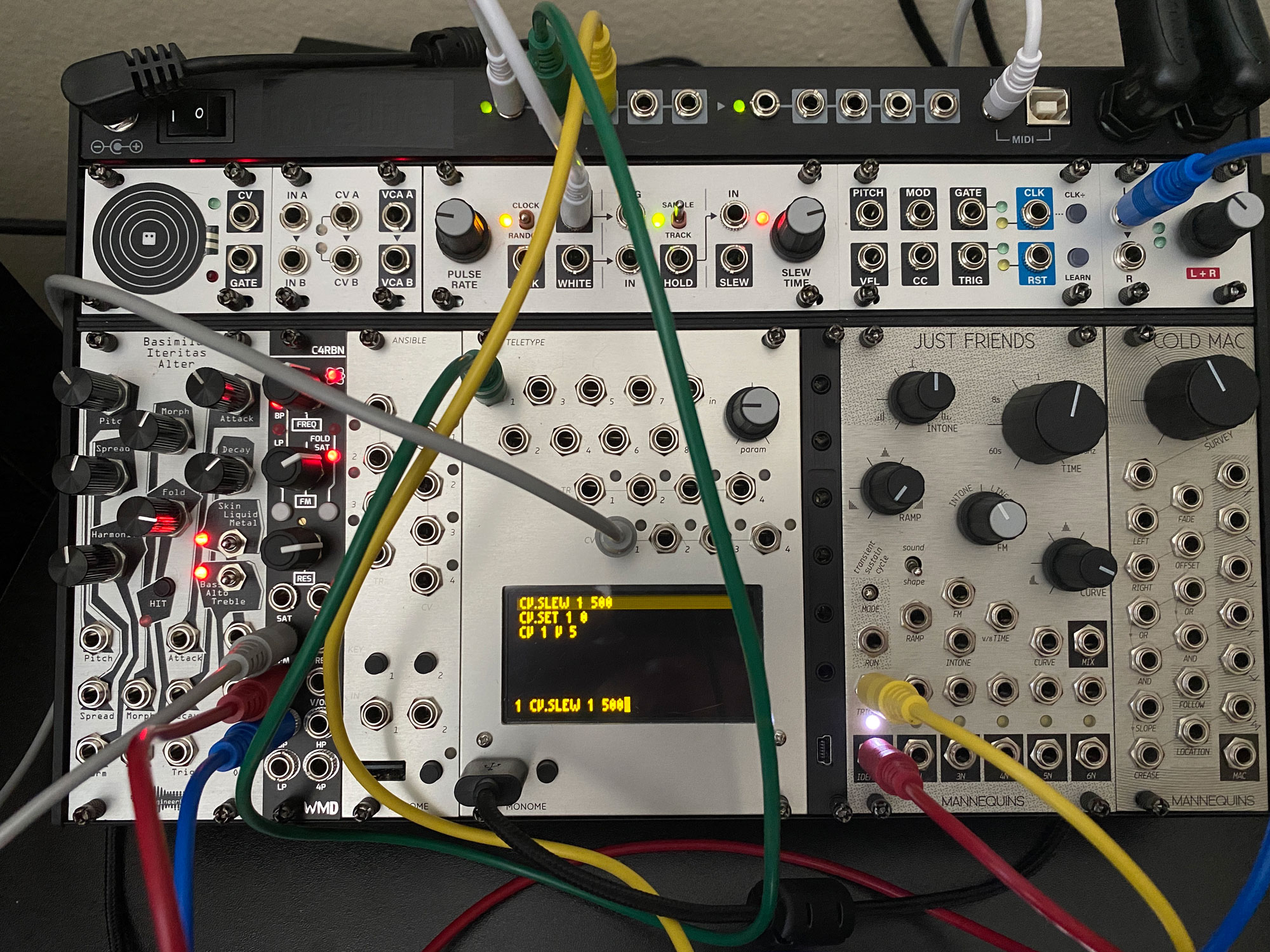
- White Cable: clock output (here randomized) to buff mult.
- Green Cable: clock buff mult to Teletype in #1.
- Grey Cable: Teletype CV #1 output to filter frequency modulation input.
- Yellow Cable: clock buff mult to envelope trigger input.
- Red Cable: envelope output to filter input.
- Blue Cable: Filter output (here band pass) to audio interface.
And it may sound like this:
Conclusion
Generating percussive sounds with filter pinging ruptures and problematizes our usual relationship with filters. Filters are tools of subtraction. With this simple electrical “hack” the synthesist instead gives voice to the silencer.